Brief Summary: GoldenBlades are a set of interactive rollerblades that take inspiration from the 80s to build a fun and quick way of getting around.
For: Critical Making, UC Berkeley Master Class (~2 week project)
Design by: Diego Rivas & Daniel Lim
My contributions: Final prototype design, prototype, & assembly. Electronics embedding and troubleshooting. Overall architecture of product concept.
Functionality Links: Speed controlled light, Wireless control of lights
DESIGN + FABRICATION
1. Sketching
Outline the components that will be needed, rough dimensions, assembly process and divide tasks. This part is key in the process to allow the designer to visualize and iterate on. On the left we sketch out the overall aesthetics, while on the right we list out our Bill of Materials.

2. Low-Fidelity Prototyping
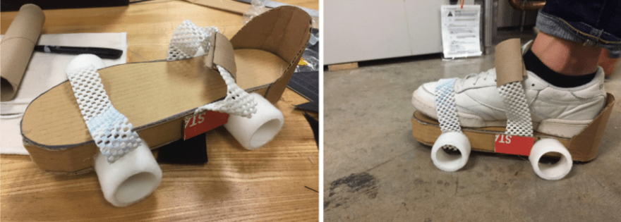
In this stage we turn very raw materials into a three-dimensional representation of our idea. For our process we started with a chicken wire model, and moved onto a cardboard. In this stage we used an exacto knife, cardboard, and some elastic materials with hot glue. With this design, we check the dimensions to then move onto a next version prototype.
3. Dimensions to digital files
The next step is taking dimensions of the cardboard prototype and passing that onto digital files. To do this, we simply take a picture next to a measurement device (such as a ruler or a caliper) and then upload that to a program that can generate a 2D image. In our case, we first used Adobe Illustrator to generate the digital image as shown below.
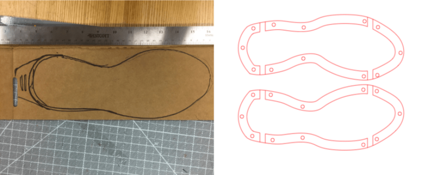
Next, two separate laser cuts were made using the file shown on the right. The first is a full outline cut done with ¼” plywood, while the second was done on acrylic for the bottom pieces, which will be shown moving forward.
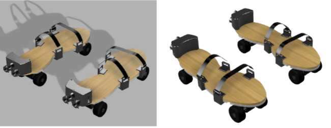
4. 2D to 3D CAD
Having the 2D dimensions, the next step is simply using Fusion 360 to make a full digital prototype. The purpose of this step is to design the parts that will be 3D printed: the rocket case in the back for the electronics, and the velcro attachments on the sides. This also allows us to scope which aftermarket rollerblades to purchase in order to take the bottom wheel set and install it onto our design.
5. 3D Prints and Assembly
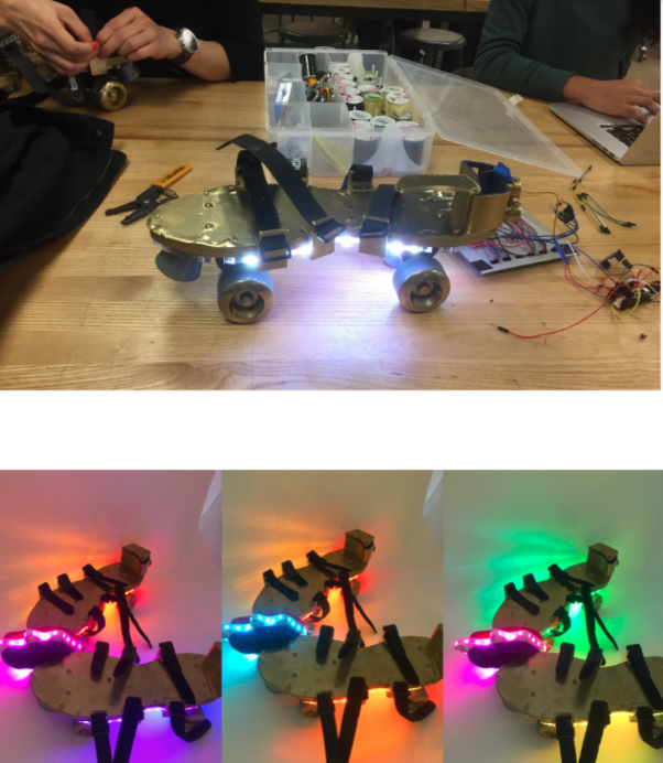
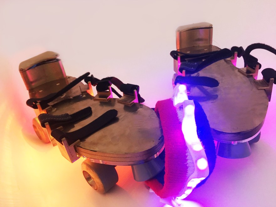
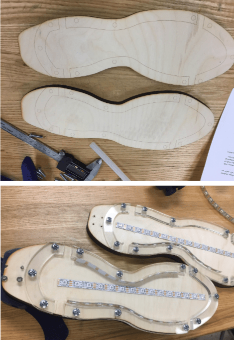
The next step is taking the STL files of the parts mentioned above and 3D printing them, which we did with the Ultimaker in the Invention Lab. Then, we started putting all of the components together, mostly with hot glue and bolts. This also included strategically mounting the Neopixel LED strips and the wheelset as it is shown below.
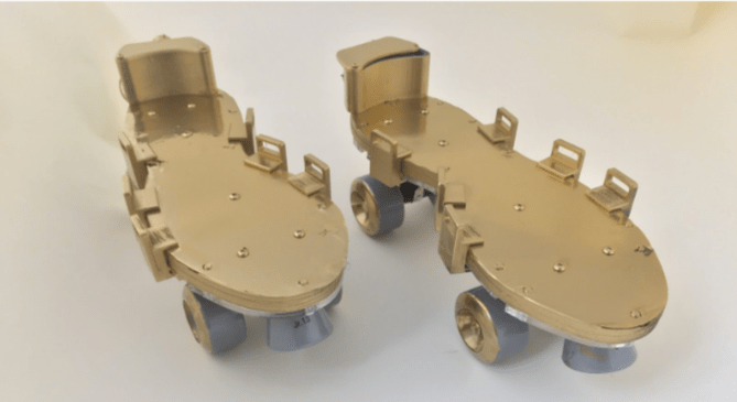
6. “Goldenization”
Our next step is strictly aesthetic, and it is driven by our ‘retro’ mission statement. We took metallic gold paint and covered the entire assembly. However, to do so, anything from the acrylic periphery down must be masked such as to ensure it will not affect the light diffusion from the LEDs.

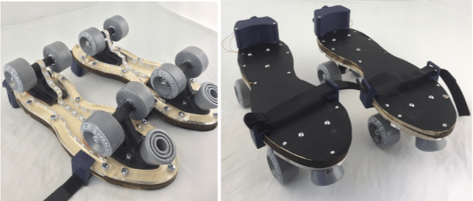
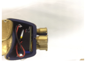
7. Hardware mount
As our next step we check the fit of the components in our enclosure, which involved strategically placing the components so the connectors would be stable but still fit.
8. Hardware test and iteration
Once the mechanical assembly is complete, all we do is place the feather and the accelerometer in the rocket case, connect it to the LEDs and to a battery and let it run! This stage refers to making sure that the accelerometer data is corresponding to the right LED change, which is fully laid out in the code file.